Institute of Chemistry, Academia Sinica – Research
使用綠色溶劑以溶液剪切塗佈法製備之高效率且可放大之鈣鈦礦太陽能電池
High-Efficiency and Scalable Solution-Sheared Perovskite Solar Cells Using Green SolventsChem. Eng. J. 2022, 437, 135477. Gizachew Belay Adugna, Seid Yimer Abate and Yu-Tai Tao*
再生能源,例如太陽能,是能源供應的未來。在本研究中,我們展示在鈣鈦礦太陽能電池技術的新進展。使用比較環保而低沸點的 CH3CN 為溶劑,在攝氏45度基版溫度及空氣環境下,以簡單而且可以放大的溶液剪切塗佈法製備出大面積 (10x10 平方公分) 而且高品質均勻的鈣鈦礦膜。在此溫度下所得鈣鈦礦結晶聚集範圍及顆粒邊界都較小,相形之下以傳統 DMF/DMSO 為溶劑在 140 度高溫下製備的薄膜,結晶區域間隙、缺陷則大得多。我們進一步能在FTO基版上將電池元件 Spiro-OMeTAD/MAPbI3/mp-TiO2/c-TiO2 的各層都用剪切塗佈法製備。以此種全塗佈的薄膜製成的太陽能電池能量轉換效率在標準面積(0.04平方公分)下為 17.77%,在較大面積 (1.5平方公分) 下為13.41%。這結果顯示鈣鈦礦太陽能電池技術可以進一步製備大面積元件及製造模組,乃至其商業化生產。
Renewable energy sources, such as solar energy, hold the future of our energy supply. In this study, we have demonstrated our progress in solar cell based on perovskite. A high-quality and homogeneous perovskite layer over a larger area (10x10 cm2) can be prepared via the simple and scalable solution-shearing process in ambient air using the greener and more volatile acetonitrile solvent at a lower substrate temperature of 45˚C. Crystalline perovskite film with much reduced domains and grain boundaries was obtained at this low temperature, in contrast to the sheared perovskite film from the conventional DMF/DMSO solvent at an elevated temperature of 140˚C, which led to wider domain boundaries and more defects. Furthermore, uniform layers over the large area were also prepared by sequential shearing of all layers in the device of Spiro-OMeTAD/MAPbI3/mp-TiO2/c-TiO2 on FTO substrate using green solvents. The solar cell based on the all-solution-sheared films offered outstanding device power conversion efficiency of 17.77% (on 0.04 cm2 area) and 13.41% for a large active area(1.5 cm2 area). These results highlight the potential of upscaling and module fabrication and eventual commercialization of perovskite-based solar cells.
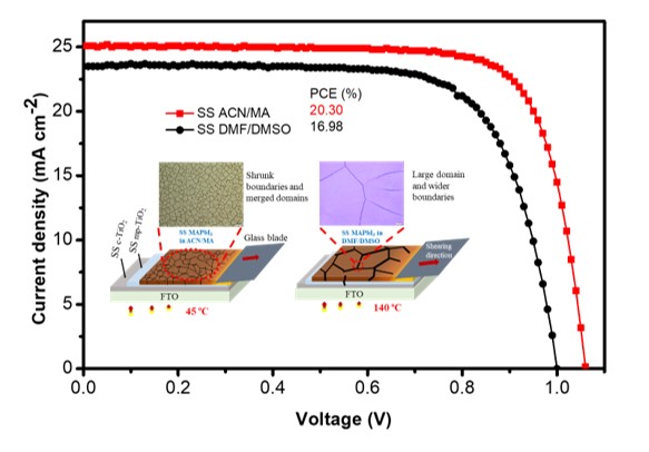
Figure 1. Morphology of perovskite films sheared from two distinct solvent systems and their device performance.
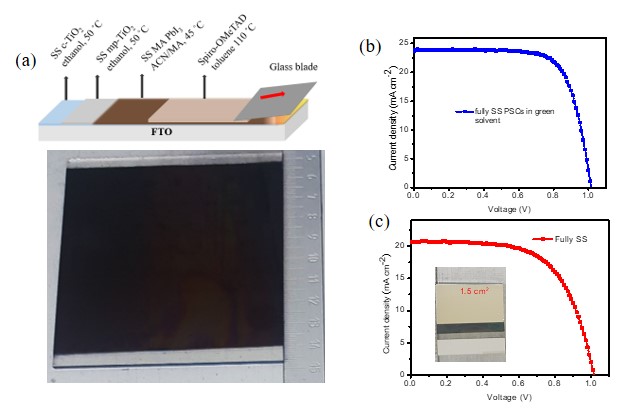
Figure 2. (a)Scheme and photograph of all-sheared layers from green solvents. (b,c) J-V curves for standard size and larger active area PSCs from the corresponding sheared layers